
3 The AI-Native Design Life Cycle
“All models are wrong, but some are useful.”
— George E. P. Box, Robustness in the Strategy of Scientific Model Building (1979) (Box 1979)
Box, George E. P. 1979. “Robustness in the Strategy of Scientific Model Building.” In Robustness in Statistics, edited by Robert L. Launer and Graham N. Wilkinson. Academic Press. https://doi.org/10.1016/B978-0-12-438150-6.50018-2.
Author’s Note. George E. P. Box originally applied this aphorism to statistical models. Because every model simplifies reality, our working question is always whether that simplification still serves the decision at hand. Whether we build a task description, benchmark, simulator, power model, or test suite, we inevitably omit specific details. Each tool remains useful provided we understand its scope and ensure our decisions do not exceed what the evidence supports.
North-Star question
AI can generate more candidates and invoke more tools than any architect can manually inspect. How must the work be organized so that promising outputs become defensible design decisions rather than an uncurated volume of unverified artifacts?
As systems architects, we constantly blend explicit artifacts with tacit knowledge (unwritten experience and architectural intuition) (Polanyi 1966). Established architecture practice already combines expert judgment with structured requirements, automated sweeps, simulation infrastructure, verification plans, and formal review. Even so, requirements, models, and review notes capture only part of the reasoning, and experienced engineers still supply crucial context from memory. Today’s learned tools can assist with proposing candidates, screening local choices, and coordinating selected tool actions. The broader Architecture 2.0 program asks how to organize those capabilities across a complete workflow without claiming that autonomous full-stack design is already routine.
Polanyi, Michael. 1966. The Tacit Dimension. Doubleday.
Amodei, Dario, Chris Olah, Jacob Steinhardt, Paul Christiano, John Schulman, and Dan Mané. 2016. “Concrete Problems in AI Safety.” arXiv Preprint arXiv:1606.06565.
Goodhart, Charles A. E. 1975. “Problems of Monetary Management: The UK Experience.” In Papers in Monetary Economics, vol. 1. Reserve Bank of Australia.
Generative models can propose heterogeneous subsystem candidates far faster than manual review can absorb them. However, without a disciplined life cycle, automated tools can subtly shift the research question, submit invalid microarchitectural configurations, or accept a clean tool execution that recorded no valid measurements. They might optimize a misleading proxy metric (Amodei et al. 2016; Goodhart 1975) or extrapolate a result beyond its generating conditions. If we rely solely on a raw sequence of ad hoc prompts and unmonitored tool invocations, we lose visibility into where these failures occur.
Because each pitfall demands a different repair, we must organize workflows to catch errors early. Established systems engineering processes divide iterative technical work, enabling teams to review progress and backtrack to whichever step needs revision (Hirshorn et al. 2017). We apply that foundational principle here. The six life-cycle responsibilities (Formulate, Explore, Implement, Evaluate, Interpret and Explain, and Review and Decide) are not isolated steps in a waterfall process. They form the connected stages of our design loop. To prevent automated tools from flooding us with unverified candidates, we document these iterations in a Design-Loop Card, which binds each attempt to its target question, allowed actions, tool budget, and rejection checks. We view each phase as asking a distinct question and leaving a concrete result for the next architect to review.
Hirshorn, Steven R., Linda D. Voss, and Linda K. Bromley. 2017. NASA Systems Engineering Handbook. NASA/SP-2016-6105 Rev 2. National Aeronautics; Space Administration. https://ntrs.nasa.gov/citations/20170001761.
Learning objectives
This chapter establishes the following learning objectives:
- Contrast ad hoc AI prompts with rigorous architecture methods across hardware and software subsystems.
- Define the six life-cycle responsibilities, outputs, and targeted repair paths.
- Manage iterative design loops without relying on rigid waterfall schedules.
- Distinguish a complete life cycle, scoped study, design loop, and study record.
- Preserve design context to keep all evidence, tool executions, and failures reviewable.
3.1 Six Core Responsibilities
When automated workflows propose candidate configurations in volume, root-cause failure diagnosis becomes a central architectural challenge. If an invalid memory interface, a malformed simulation script, or an under-constrained power model all trigger a generic error, we waste compute attempting indiscriminate retries. To maintain control over design automation, we must isolate failure domains into explicit responsibilities. Repairing a flawed research question requires a different path than fixing an illegal microarchitectural parameter or an unmodeled simulator artifact. When we assign each failure mode to its owning stage, every defect routes directly to the work that can fix it.
Design principle: Isolate failure domains to enable targeted repair
The principle: Structure the AI-native design life cycle so that independently failing outputs belong to distinct responsibilities.
The application: Route any inadequate result directly back to the responsibility that owns its repair, preserving original design questions, selected candidates, tool configurations, and valid prior results to prevent redundant computation and global state corruption.
- Formulate. Translates intent into a precise architectural question, legal bounds, and explicit verification checks.
- Explore. Identifies valid candidate configurations across coupled subsystem design spaces.
- Implement. Prepares candidate configurations for execution by relevant simulator and synthesis tools.
- Evaluate. Compares raw tool measurements against declared constraints and multi-objective targets.
- Interpret and Explain. Identifies true physical mechanisms accounting for observed performance and power differences.
- Review and Decide. Renders an actionable decision (advance, revise, reject, or stop) backed by the complete study record.
To ground these responsibilities, we examine a prospective integrated mobile Extended Reality (XR) System-on-Chip (SoC) design effort targeting a TSMC 3 nm-class low-power process node. This SoC targets real-time spatial tracking and neural rendering under a strict 3 W Thermal Design Power (TDP) envelope, integrating heterogeneous RISC-V RV64GCV application cores, dedicated neural processing unit (NPU) tile arrays, and high-bandwidth UCIe chiplet links across the eight prompt stack layers introduced in Section 1.4.2.
The six life-cycle responsibilities map architectural intent to a reviewed decision while isolating failure domains (Figure 3.1). Forward handoffs carry concrete artifacts between adjacent stages, while targeted return arrows route inadequate outcomes directly back to the owning responsibility. If a simulator run crashes due to malformed parameters, our repair path returns the work to Implement without discarding the candidate. If a constraint proves unfeasible, the path returns to Formulate. This explicit routing carries our design intent to a reviewed next action without forcing us to restart the study from scratch.
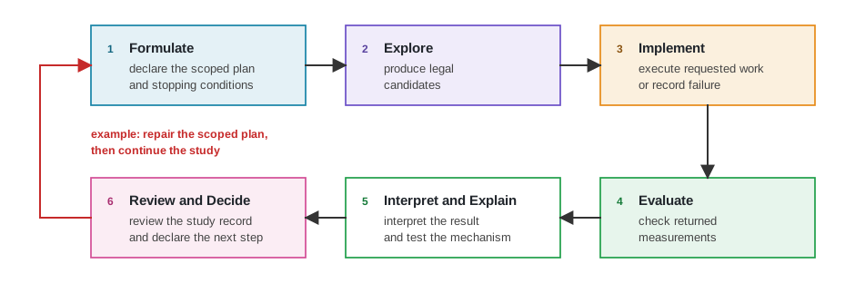
In one complete pass, we convert design intent into a scoped plan, legal candidates, executed tool work, checked results, a supported account, and a reviewed next action. Rapid iteration can blur the scale of our work, so we use four terms to distinguish our complete effort from the parts that repeat.
Four terms recur throughout the book, and they differ in what each names: the responsibilities themselves, one application of them, the path through them, and the account they leave behind.
- Life cycle: Names the complete set of responsibilities we need to move from intent to a defensible decision.
- Scoped study: Applies those exact responsibilities to one specific architecture question and one intended decision.
- Design loop: Describes our iterative path through the relevant responsibilities as our design changes and feedback returns.
- Study record: Preserves our core question, attempts, observations, conclusions, and unresolved issues so another architect can inspect our work.
This clear distinction determines exactly what we can reuse and what we must redo. For example, if our baseline simulation result used an obsolete memory model, our scoped study still defines the core question. Our design loop routes the comparison back to the specific work needing repetition, and our study record preserves why the old result no longer applies.
We formalize these verification boundaries in Table 3.1: for each stage it names the input artifacts the stage receives, the deliverables and validation checks it must produce, and the precise return path taken when an output falls short.
Across all six rows, a stage boundary proves useful because the work on either side can fail independently. For instance, Implement converts candidate configurations into verified execution records. If an execution script fails, column 4 routes the work back to tool infrastructure setup without altering the candidate. Similarly, Evaluate checks verified execution records against declared constraints, routing measurement failures back to the evaluation plan while rejecting invalid candidates. These explicit seams prevent local infrastructure crashes from masquerading as architectural rejections.
| Stage | Receives | Produces and checks | Inadequacy and repair routing |
|---|---|---|---|
| Formulate | Product intent, a design question, and known requirements. | A scoped plan declaring question, comparator, scope, constraints, and exclusions. | Route an inadequate plan back to intent or scope refinement. |
| Explore | Scoped plan and declared legal design space. | One or more legal candidates and search trajectory record. | Route an illegal candidate or uninformative search back to legal design space boundaries. |
| Implement | Candidate configuration, requested tool work, and input schemas. | An execution record showing requested work ran on intended state. | Route an unexecuted or malformed tool run back to request or tool infrastructure setup. |
| Evaluate | Verified execution record, planned metrics, and validity conditions. | A comparison stating which checks passed, failed, or remain unresolved. | Route a measurement failure back to the measurement plan; reject candidate if checks fail. |
| Interpret and Explain | Checked result and proposed physical mechanism. | An account supported, revised, or contradicted by direct physical reasoning. | Route an unverified mechanism back to hypothesis testing or request additional observations. |
| Review and Decide | Scoped plan and complete study record. | Actionable decision (advance, reject, revise, or stop) within declared scope. | Reopen the stage owning missing evidence or close the study cleanly. |
Each responsibility needs enough clear information for us to judge its result, inspect exactly what happened, and quickly identify the correct repair when the outcome is inadequate. Formulation comes first because our legal alternatives must exist before exploration can propose candidates.
3.2 The Six Life-Cycle Stages
The six responsibilities defined above now become six working stages, examined one at a time. Each stage converts its inputs into inspectable artifacts, establishing explicit verification boundaries before handing work to the next phase. Below, we walk through these six stages to examine how architectural intent evolves into verified evidence and defensible design choices.
3.2.1 Stage 1. Formulating Core Architecture Questions
Every architecture study begins with high-level intent, yet converting a vague goal like optimizing real-time spatial tracking into an actionable design space determines whether an engineering study succeeds or fails. Without explicit scope, declared comparators, and hard constraints, automated search algorithms optimize misleading proxy metrics or propose illegal microarchitectural configurations. Formulation transforms raw intent into a precise architectural question bound by machine-readable component metadata contracts (such as IP-XACT / IEEE 1685) and strict hardware-software contracts. When we define component metadata, bus interfaces, register maps, and memory-mapped address spaces up front, we establish what software can safely assume and what hardware must reliably deliver. A scoped plan establishes these requirements before any search space exploration begins, fixing the concrete parameters our mobile XR SoC study assigns (Table 3.2). The contract establishes our core Question comparing 3 MiB and 4 MiB L2 cache candidates against our 2 MiB baseline under strict Hard constraints (a 3 W TDP envelope, a \(1.5\text{ mm}^2\) SRAM macro area limit, and a 2.5 ns access latency bound).
The same contract specifies our objective, workload conditions, planned checks, and a strict budget of four cycle-level execution attempts. We use one versioned XRBench trace and one pinned RV64GCV software image. gem5 measures frame-time, cache, and memory-system behavior; a declared SRAM model estimates area and access time; and Verilator checks functional behavior for any candidate that advances. Fixing those declarations lets us enumerate this small legal space directly and report the observed comparison without claiming a complete Pareto frontier.
| Declaration | Prospective mobile XR SoC subsystem study |
|---|---|
| Question | Which 3 MiB and 4 MiB L2 candidates should advance to RTL evaluation for the declared XR workload? |
| Comparator | The current 2 MiB baseline. |
| Scope | One subsystem capacity decision inside the XR compute block. |
| Permitted changes | L2 capacity may take values 2 MiB, 3 MiB, or 4 MiB. Banking, NPU tile buffers, core count, compiler flags, interfaces, and clocking remain fixed. |
| Hard constraints | Modeled subsystem power must not exceed 3 W. The SRAM macro must not exceed \(1.5\text{ mm}^2\) and its access time must not exceed 2.5 ns. |
| Objectives | Reduce 99th-percentile frame time while limiting added power and area. |
| Conditions | One versioned XRBench trace, one RV64GCV RISC-V software image compiled with a pinned LLVM toolchain, and recorded model and tool versions. |
| Planned checks | Estimate SRAM area and access time with the declared SRAM model; measure 99th-percentile frame time, cache behavior, and memory traffic in gem5; run the functional regression suite in Verilator for any candidate that advances. |
| Budget | Four cycle-level gem5 execution attempts in total. One attempt is reserved to replace an infrastructure-invalid run; if no replacement is needed, the study ends after the three declared configurations. Analytical and RTL checks are costed separately. |
| Stopping conditions | Stop when the intended decision is resolved or the run budget is spent. |
| Intended decision | Recommend at most one subsystem capacity configuration for a later gate-level RTL study. |
| Exclusions | Subsystem clock domain changes, prefetching algorithms, thermal signoff, and product-level cost. |
Formulation ends in an architectural claim, which makes the expected result falsifiable.
Architectural claim. An architectural claim states the proposed mechanism, expected outcome, scenario, comparator, alternatives, requirements, and evidence that would count against it.
Our claim forces us to make the connection between mechanism and system-level outcome something our multi-tool measurements must test. As our study proceeds, we must keep all requirements traceable. A 3 W limit only becomes operational when we name our units and conditions and explicitly assign the validation check at the consuming interface.
3.2.2 Stage 2. Exploring Alternatives
Once we bound our architecture question, exploration must remain inside the declared legal space. This example contains only three L2 capacities, so enumeration is more defensible than introducing a search method. Larger studies may span compute tile counts, buffer partitions, compiler choices, and other coupled variables, but adding any of those here would change the question and require a new formulation. When a larger study does compare several objectives, a candidate is non-dominated on the observed Pareto set when no evaluated alternative improves one objective without worsening another (Deb 2001).
Deb, Kalyanmoy. 2001. Multi-Objective Optimization Using Evolutionary Algorithms. John Wiley & Sons.
Exploration systematically covers the declared legal design space using explicit parameter representations while pruning invalid configurations early. In this study, that means evaluating the three legal L2 capacities and changing nothing else. In a broader study, discrete grids, Abstract Syntax Tree (AST) compiler mutations, Control-Data Flow Graph (CDFG) schedule transformations, or continuous surrogate bounds may represent additional choices. The exploration record must still show which cases we evaluated, which regions we pruned, and what remains unexplored.
Legal does not mean independent. When we increase capacity in one subsystem, we alter access time, banking, interconnect distance, leakage, floorplan pressure, and the software-visible benefit of another optimization. We explore coupled alternatives rather than selecting uncoordinated parameters across CPU cores, NPUs, memory, and software compilers. We record why we sampled or pruned each region and which dependency drove that choice. If a coupling changes a declared workload, interface, constraint, or legal action, the study returns to formulation.
3.2.3 Stage 3. Implementing Testable Representations
A promising candidate on paper or in a parameter dictionary cannot yield empirical evidence until it is translated into an executable representation. Implementation bridges abstract parameter selections and concrete tool execution by instantiating transaction-level models, generating synthesizable RTL, and compiling target software binaries. Transaction-level interconnect handoffs between IP blocks rely on SystemC TLM-2.0, an IEEE standard transaction-level modeling framework, using socket and generic payload schemas to model memory-mapped bus transactions across heterogeneous subsystems. Synthesizable RTL blocks and interconnect wrappers are formatted into synthesizable SystemVerilog, while software images are packaged alongside explicit ISA extension flags.
To support replay and later reproducibility attempts, every tool invocation produces an execution record, an immutable structured audit log joining authorized requests, scheduler jobs, input parameters, execution status, returned artifacts, computational costs, and terminal failure causes into a single inspectable object.
We must confirm that each tool actually used our requested parameters. A syntactically valid configuration can deceive us by selecting the wrong top-level module or skipping the precise workload region that defines our comparison. This distinguishes an infrastructure failure from a candidate failure. If a simulator crashes or a script is malformed, we only know that our requested test failed to run correctly. These infrastructure execution failures provide no evidence regarding the quality of our architectural candidate. Only a valid execution produces a result we can trust to evaluate or reject a design. The stakes here are old and documented. Data General’s Eagle team invested months in a microcode simulator that had to behave like the real machine precisely so that debugging against it would mean anything, with scarce prototype hardware driving the investment (Kidder 1981).
Kidder, Tracy. 1981. The Soul of a New Machine. Little, Brown; Company.
Failure mode: The zero-cycle simulation artifact
The trap. Early simulation runs report zero-cycle latency and flawless execution across complex instruction routines, and the team reads a microarchitectural breakthrough instead of a broken model.
The mechanism. The simulator’s model omits or misinitializes exactly the machinery that costs time, a clock model, a bus handshake, an arbitration queue, and a downstream parser substitutes default zeros for the wait states that were never simulated. We present this as an illustrative composite rather than a single documented incident.
The lesson. We must recognize zero-latency returns as infrastructure execution failures rather than microarchitectural breakthroughs. A rigorous implementation check confirms that clock models, bus handshakes, and memory requests exist before our evaluation interprets returned metrics.
3.2.4 Stage 4. Evaluating Candidate Evidence
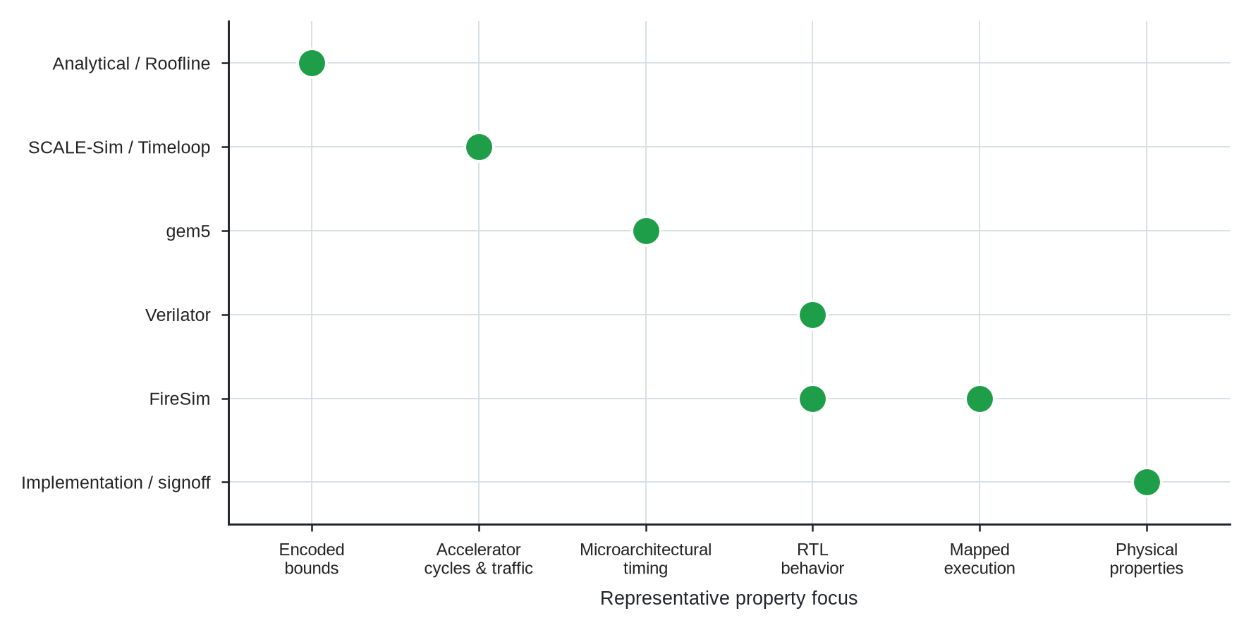
Once implementation confirms that our tool execution completed cleanly, we turn to evaluating candidate evidence against declared design constraints. Architectural evaluation trades turnaround against the properties each tool can observe. No single tool can simultaneously model cycle-accurate DRAM queueing, RTL functional assertions, and gate-level static timing across millions of workload cycles within a practical runtime envelope. Evaluation therefore combines specialized tools and interprets each return against the power, performance, area, timing, or correctness question it was configured to examine.
The tools in Figure 3.2 do not form a single ranking toward architectural truth. They expose different properties at different costs. Analytical models can reject candidates against encoded bounds. SCALE-Sim and Timeloop focus on accelerator cycles, utilization, and traffic under their models. gem5 exposes configured microarchitectural timing, while Verilator executes RTL behavior under a supplied harness. FireSim accelerates a mapped target model, and implementation or signoff flows examine selected physical properties under declared libraries, constraints, modes, and corners.
Those paths can still be staged economically. Cheap bounds reject candidates before expensive runs, while later checks target properties the earlier models did not observe. Handoffs to implementation tools exchange cell timing, dynamic power, leakage, and pin-capacitance data through Liberty (.lib) libraries. The resulting power estimate remains conditioned on activity, parasitics, libraries, operating modes, and corners. Staging controls cost; it does not make one tool’s return a more complete version of another’s.
Stronger evidence for one property never widens our decision scope by itself. A cycle-level result in gem5 does not authorize full silicon fabrication if our study only promised a recommendation for gate-level RTL evaluation. Our evaluation can end in several legitimate states. We must keep invalid executions, unresolved comparisons, and rejected candidates visible for subsequent review.
We must declare tool comparability study by study. Software engineering benchmarks like SWE-bench, an evaluation framework for software engineering tasks (Jimenez et al. 2024), evaluate functional state using a single test harness, but architecture evaluation lacks any single test that simultaneously resolves performance, power, area, timing, physical feasibility, and system-level trade-offs. Instead, we aggregate feedback across a spectrum of specialized tools.
Jimenez, Carlos E., John Yang, Alexander Wettig, et al. 2024. “SWE-bench: Can Language Models Resolve Real-World GitHub Issues?” International Conference on Learning Representations (ICLR). https://doi.org/10.48550/arXiv.2310.06770.
Binkert, Nathan, Bradford Beckmann, Gabriel Black, et al. 2011. “The gem5 Simulator.” ACM SIGARCH Computer Architecture News 39 (2): 1–7. https://doi.org/10.1145/2024716.2024718.
Karandikar, Sagar, Howard Mao, Donggyu Kim, et al. 2018. “FireSim: FPGA-Accelerated Cycle-Exact Scale-Out System Simulation in the Public Cloud.” 2018 ACM/IEEE 45th Annual International Symposium on Computer Architecture (ISCA), 29–42. https://doi.org/10.1109/ISCA.2018.00014.
Consider two design teams analyzing the exact same system trade-off. One team might select gem5 (a modular cycle-accurate architectural simulator), while the other uses FireSim (an FPGA-accelerated full-system RTL simulation platform) (Binkert et al. 2011; Karandikar et al. 2018). Either team can compare subsystem throughput and execution latency. However, if we require energy estimates or physical area metrics, we must attach separate models and state our underlying assumptions explicitly. Simply choosing a tool does not reveal which workload phases we measure or whether we faithfully executed the same baseline. Explicit declarations determine whether our two teams performed an identical study. As architects working alongside automated methods, we must carry these declarations clearly through candidate selection, tool requests, execution, and verification checks.
3.2.5 Stage 5. Interpreting and Explaining Empirical Results
A passing evaluation score demonstrates that a candidate satisfied declared quantitative metrics, but it leaves an architectural question unanswered. We must determine whether our proposed hardware mechanism drove the performance gain or whether the candidate merely exploited a simulator artifact. Evaluation produces raw numbers; interpretation extracts physical understanding. Stage 5 decouples top-line metric improvements from tool measurement anomalies, isolating the true microarchitectural drivers behind observed performance gains.
A larger cache capacity might improve average latency but degrade tail latency due to NoC contention or compiler thread scheduling. We connect measured outcomes to a concrete physical account rather than relying on speculative narrative explanations. When we interpret performance, we explicitly isolate simulator measurement artifacts, such as simplified queueing models, unmodeled DRAM refresh delays, or idealized bus arbitration, from true physical hardware gains.
Simulation fidelity gaps exist across all subsystem domains. An optimizer in SCALE-Sim might achieve throughput by omitting weight buffer sync barriers, causing data hazards. A compiler pass in TVM (an open-source deep learning compiler framework) might eliminate vector spill code in simulation by assuming unconstrained register file capacity, failing when compiled for target hardware in Verilator.
An improved top-line metric differs from a proven physical mechanism. We should choose required observations before we trigger an expensive run. A top-line score cannot recover miss classifications or per-frame histories discarded along the way. While fluent prose can organize our final account, it can never replace the empirical measurements that support it.
3.2.6 Stage 6. Reviewing and Deciding Handoffs
The final stage of our life cycle bridges empirical evidence to an architectural recommendation and, when warranted, an organizational commitment. An extensive collection of simulation logs and Pareto curves does not automatically constitute either. The architect judges what technical recommendation the evidence supports. A named commitment authority then decides whether the organization should advance the candidate toward RTL synthesis or silicon tapeout. Review synthesizes the exploration trajectory, qualified evaluation evidence, physical explanations, and residual risk into a study record that supports both judgments without conflating them.
Through review, we might advance one candidate, reject another, or request an entirely new comparison. We may revise the original question, narrow our conclusion, or simply stop because we exhausted our budget. An honest, unresolved result remains a useful outcome provided our study record clearly explains why the question remains open.
When a result is missing, we must know whether to propose another candidate, repair a tool run, collect another measurement, or narrow our decision. That choice relies directly on the explicit stage contracts and repair routing we established in Table 3.1.
During review, we choose actions solely within our assigned authority. While our system might propose a candidate, it cannot override human judgment. When review calls for revision, we name the responsibility that reopens the task, taking care to preserve the requirements and tool conditions from which the repaired work proceeds.
3.3 Managing Architectural Revisions
When an architectural attempt requires refinement, we rely on targeted return paths that route inadequate outputs directly back to the specific responsibility owning the repair. The design loop executes those targeted revisions across the six life-cycle responsibilities while preserving valid prior work (Figure 3.3).
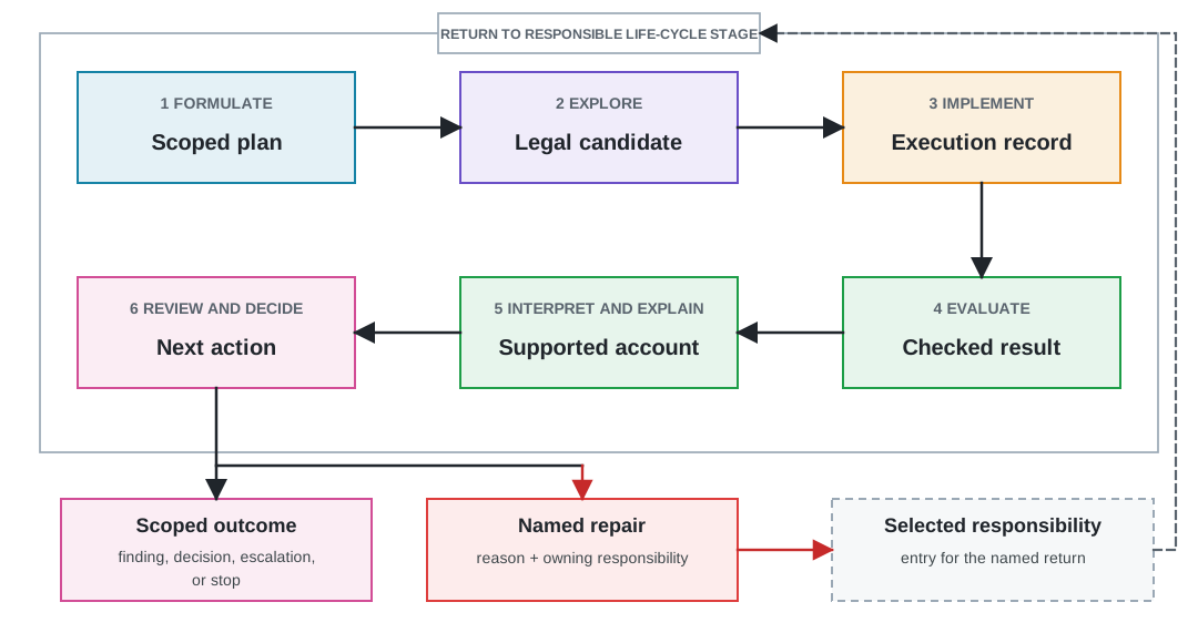
As work moves forward, backward return paths route repairs to the owning stage without discarding valid exploration history, ensuring every design revision preserves historical evidence while holding every change accountable to our original question.
When we conduct parallel work, we preserve the same study state across branches. We merge results only after verifying that their assumptions, interfaces, and permitted changes remain compatible. When a change invalidates a result, we do not erase the data, but we prevent that outdated result from silently carrying forward as current evidence.
Every loop we run also needs a defensible way to end. Our scoped plan declares the stopping conditions up front, and the design loop honors them. We stop when the intended decision is resolved, when the run budget is spent, when every legal candidate has been rejected, or when feedback shows that the question itself needs reformulation. In the L2 capacity study, three valid cycle-level executions cover the baseline and two alternatives. A fourth attempt may replace one infrastructure-invalid run, but it may not expand the legal space or rescue an unfavorable comparison. If the three valid executions leave the 3 MiB and 4 MiB candidates indistinguishable on 99th-percentile frame time under the declared conditions, we close the study with an unresolved verdict or return to formulation to sharpen the question.
Convergence and churn can look alike from inside the loop. When successive iterations change the candidate ranking without changing the decision, the loop has converged and further work buys nothing. When successive iterations keep reopening formulation, the problem is not the loop’s speed but its question. We watch for both signals, and we treat a loop that cannot stop as a formulation defect rather than an evaluation shortfall.
Stopping is a result, not a failure. A study that ends with a resolved decision, a rejected slate, or an honest statement that the available measurements cannot separate the candidates leaves the next architect better off than a loop that keeps consuming simulation budget in search of a preferred answer. The temptation to run one more sweep grows precisely when the evidence is weakest, which is why we bind the budget before the first candidate is proposed and record the stopping reason in the study record.
3.4 Design-Loop Cards and Documentation
While targeted return paths route design revisions to the correct stage, we still need an operational mechanism to track how these tool executions evolve. As automated methods generate and test many subsystem variants, maintaining transparent design provenance becomes a central governance challenge. Without a structured record, automated exploration degenerates into uninspectable shadow state. To establish clear architectural accountability, we introduce the Design-Loop Card, a standardized index that binds automated tool execution directly to human design intent, qualified evidence, and explicit approval rights.
We adapt the reporting methodology of model cards and datasheets for datasets, tools that make intended use and known limits readily reviewable (Mitchell et al. 2019; Gebru et al. 2021). Because our designs evolve rapidly, our architecture studies must preserve the changing design state, tool conditions, failed checks, and the explicit authority for the next action. To manage these dynamic requirements, our study record makes our architectural state and its revisions fully inspectable.
Mitchell, Margaret, Simone Wu, Andrew Zaldivar, et al. 2019. “Model Cards for Model Reporting.” Proceedings of the Conference on Fairness, Accountability, and Transparency, 220–29. https://doi.org/10.1145/3287560.3287596.
Gebru, Timnit, Jamie Morgenstern, Briana Vecchione, et al. 2021. “Datasheets for Datasets.” Communications of the ACM 64 (12): 86–92. https://doi.org/10.1145/3458723.
Study record. The cumulative account of one scoped architecture study. It retains the plan, stage outputs, failed or unevaluated work, unresolved questions, stopping reason, and supported decision, with links to the detailed artifacts needed for review or replay.
For every consequential transition, our study record explicitly names the revision. It details exactly who or what proposed and approved the action, what executed it across our tool flows, what checked the result, and what later change might invalidate it. We capture the specific decision being supported, the physical assumptions bounding our results, and the named authority empowered to act on them.
A three-layer architectural hierarchy connects high-level project goals to low-level tool execution (Figure 3.4). Architecture Intent & Judgment captures overarching product requirements, rationale, and the accountable decision owner. Beneath it, the Scoped Architecture Study acts as a structured container, binding our core question, scope, architectural claim, linked artifacts, tool returns, supported findings, and operational limits into an inspectable unit. Multi-Tool Execution Flows organize our implementation tools across cycle-level simulators, compiler runtimes, RTL generators, and physical EDA signoff flows.
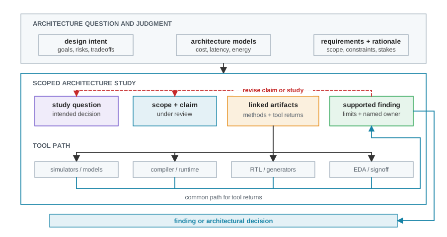
Returns from all four bottom-layer tool families feed directly back into the central study container, enabling us to synthesize multi-tool evidence into a supported finding. We use the study question to pinpoint the exact comparison, while our intended decision explains precisely why we run it. We lean on cycle-level simulators to evaluate architectural behavior, compilers and runtimes to expose software interactions, RTL generators to produce executable designs, and physical EDA flows to measure dynamic power and area. When we place the scoped study container between high-level intent and low-level execution tools, we prevent raw simulator outputs from masquerading as finished design choices, ensuring every decision remains backed by traceable evidence.
A specified Design-Loop Card for the prospective mobile XR L2 capacity study shows how this compact tabular index would organize a complete study record (Figure 3.5).
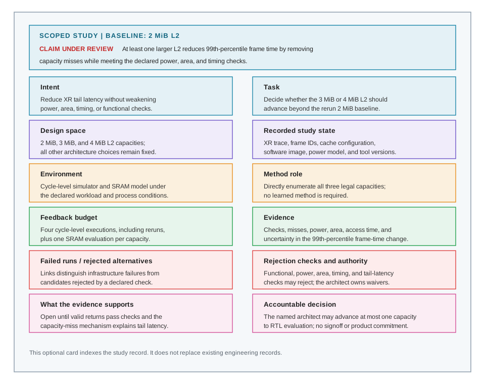
The card keeps architectural provenance legible by separating three concerns. An architectural claim anchors the evaluation by defining our target scenario, baseline comparator, and expected metrics. Execution provenance is tracked separately, indexing evaluated candidates, infrastructure execution failures, and quantitative rejection checks as the study executes, so that tool script crashes are never misclassified as rejected candidates. Empirical evidence support stays isolated from the accountable decision authority, recording what the returned measurements would support alongside the named architect empowered to approve the handoff. When we summarize intent, execution history, and decision authority in a standardized layout, this card provides an audit-ready index into our underlying engineering artifacts.
3.5 Common Pitfalls
With our life-cycle stages, repair routing, and documentation cards in place, we can now examine what happens when these structural boundaries are neglected. When we deploy generative AI models and automated optimization scripts across complex hardware-software stacks without strict life-cycle constraints, we introduce operational risks. Without explicit stage contracts, versioned boundaries, and audit-ready records, automated tools accelerate error propagation across subsystem boundaries. From the mechanisms above, we anticipate five recurring failure modes that threaten the integrity of our architectural decisions.
- Amplifying an unverified baseline across stages. Running thousands of candidate sweeps against an unverified baseline microarchitecture causes initial modeling errors to propagate across every downstream stage. Gathering large simulation volumes from an uncalibrated baseline produces high-confidence data for a fundamentally invalid architectural comparison.1
1 Data cascades in architecture life cycles: This compounding of early modeling errors across downstream life-cycle stages mirrors the phenomenon of data cascades in high-stakes AI systems (Sambasivan et al. 2021), where unaddressed upstream baseline flaws compound into systemic downstream failures that standard evaluation metrics miss.
Sambasivan, Nithya, Shivani Kapania, Hannah Highfill, Diana Akrong, Praveen Paritosh, and Lora M. Aroyo. 2021. “‘Everyone Wants to Do the Model Work, Not the Data Work’: Data Cascades in High-Stakes AI.” Proceedings of the 2021 CHI Conference on Human Factors in Computing Systems, 1–15. https://doi.org/10.1145/3411764.3445518.
Bypassing versioned hardware-software contracts. Automated agents can generate hardware blocks or ISA extensions against unversioned software dependencies, unstated ABI constraints, or informal memory interface rules. Generators can optimize candidates against isolated functional checks while ignoring system-level contracts like AMBA AXI5 (Advanced Microcontroller Bus Architecture, Advanced eXtensible Interface 5) interconnect handshakes, IEEE 1801 Unified Power Format (UPF) power intent, or compiler target flags.
Exploiting simulation fidelity gaps over physical reality. Learned optimizers can exploit measurement artifacts or high-level abstraction gaps in simulation tools. These algorithms maximize reward functions by selecting configurations that exploit simulator timing flaws or missing wire-delay models, producing candidate architectures that fail during gate-level synthesis. Measurement bias producing confident but wrong conclusions is a documented hazard even in carefully run human performance studies (Mytkowicz et al. 2009).
Skipping stage-gated repair paths. Architects may treat the six-stage life cycle as an unmonitored pipeline rather than enforcing explicit stage seams. When an evaluation fails or an execution fails to launch, resetting the entire study back to initial formulation discards valid exploration history and wastes compute budgets.
Operating without execution records. Automated tools and generative agents can be invoked without capturing immutable execution records. Running ad hoc prompt loops without logging tool inputs, seed values, environment flags, and raw stderr outputs creates uninspectable shadow state that prevents independent architects from auditing or reproducing claimed architectural results.
Mytkowicz, Todd, Amer Diwan, Matthias Hauswirth, and Peter F. Sweeney. 2009. “Producing Wrong Data Without Doing Anything Obviously Wrong!” Proceedings of the 14th International Conference on Architectural Support for Programming Languages and Operating Systems (ASPLOS), 265–76. https://doi.org/10.1145/1508244.1508275.
Simulation and electronic design automation (EDA) runs incur substantial computational expense. A poorly framed question can consume hundreds of compute hours before we discover that our results cannot support a sound design decision.
3.6 Open Questions
Even when we enforce stage boundaries and avoid these common pitfalls, fundamental research challenges emerge as we scale these responsibilities across autonomous multi-agent systems. As AI agents gain authority to propose RTL designs, configure simulation harnesses, and interpret execution traces, the boundary between automated exploration and human architectural governance becomes dynamic. Resolving how we automate repair routing, retain inspectable execution state, and balance early screening agility against rigorous signoff requires addressing four open challenges.
Repair routing and failure domain isolation: When multi-subsystem studies encounter failures across multiple life-cycle stages, we must determine optimal backtracking paths without invalidating clean intermediate state.
How can automated design systems diagnose root-cause stage failures when errors compound across Formulate, Explore, and Implement handoffs? An execution crash in Verilator or timing failure in
VCS(Synopsys VCS, a commercial SystemVerilog simulator) may stem from malformed tool flags in Implement, an illegal parameter combination in Explore, or an under-constrained memory specification in Formulate. The open problem is diagnostic methods that isolate the responsible stage seam and prevent redundant backtracking across clean life-cycle state.What state retention policies balance the computational cost of preserving failed tool attempts against the reviewer load of inspecting shadow state? Preserving every failed simulator run, malformed RTL attempt, and invalid surrogate candidate creates substantial storage overhead and review noise. We lack criteria for pruning uninformative infrastructure failures while maintaining immutable execution records for high-fidelity physical and verification signoff.
Proportionate life-cycle governance and independent verification: When we structure life-cycle handoffs, we must calibrate verification rigor to match decision criticality.
How can lightweight early-stage screening avoid premature life-cycle overhead while guaranteeing that no candidate reaches commitment without full stage signoff? Demanding complete IP-XACT specs, SystemVerilog assertion checks, and gate-level static timing signoff during early exploration degrades candidate throughput significantly. The open problem is a life-cycle policy that scales verification rigor proportionally from initial surrogate screening up to full physical signoff under human commitment authority.
What architectural safeguards prevent circular self-verification when the same AI agent proposes, implements, and interprets a candidate design? When a generative model drafts RTL, configures simulation scripts, and synthesizes the explanation, it risks propagating shared training biases or missing its own implementation flaws. The open problem is operational boundaries that establish distinct evidence, instruments, assumptions, and failure modes at consequential handoffs. A separate reviewer or model does not create independence when it relies on the same underlying evidence.
3.7 Summary
Our analysis of the AI-native co-design life cycle demonstrates how structured responsibilities transform unstructured candidate generation into verifiable, audit-ready architectural decisions. When we decouple problem formulation, space exploration, implementation, evaluation, empirical interpretation, and decision review, technical handoffs remain explicit and inspectable. This structure prevents tool crashes from masking as candidate rejections and stops unverified surrogate scores from substituting for physical explanations.
Our framework routes inadequate outputs directly back to the specific stage owning the repair, preserving valid intermediate state across design iterations. When we evaluate the Architecture 2.0 design life cycle, four core takeaways govern our work:
Key Takeaways: Stage Contracts and Audit-Ready Records
- Stage contract decoupling. Each life-cycle stage must maintain explicit input-output contracts, ensuring that candidate exploration, tool execution, and empirical interpretation produce inspectable artifacts rather than unrecorded internal state transitions.
- Targeted repair routing. Inadequate outputs or infrastructure failures must return directly to the specific stage responsible for the defect, preventing global state corruption and eliminating redundant re-evaluation.
- Empirical mechanism explanation. Architectural interpretation must connect top-line metric changes to concrete microarchitectural mechanisms, isolating true hardware gains from simulator artifacts or benchmark loopholes.
- Audit-ready study records. Every consequential design transition requires a version-controlled study record that documents baseline assumptions, candidate variations, tool outputs, failed runs, and named commitment authority.
This life-cycle structure operates successfully only when our engineering studies maintain current project knowledge, explicit data provenance, and rich hardware representations. How that architectural state is gathered, represented, and kept current across the design stack is the subject of Chapter 4.